Output linearization
Segmental linearization function (output track) allows to insert individual output user characteristics into intelligent transmitters.
![](../img/tabLinWy.png)
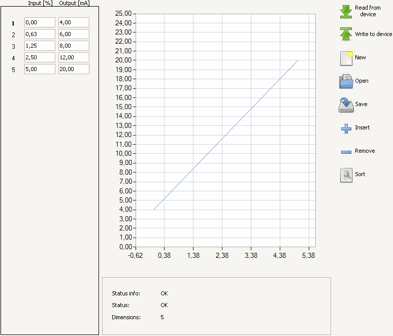
The above picture presents a user interface window.
It contains the following subareas (from the left):
- Values table
- Graphic representation of values
- The Y-axis
- input (%)
- The X-axis
- output (mA)
- buttons:
![](../img/ico/go-bottom.png)
- Read from a device – reads current linearization table from a transmitter.
![](../img/ico/go-top.png)
- Write to a device – writes a linearization table in a transmitter.
![](../img/ico/document-new.png)
- New - creates a new linearization table. The table is filled up with default values.
![](../img/ico/document-open.png)
- Open – imports a table from file.
![](../img/ico/document-save.png)
- Save – exports a table to file.
![](../img/ico/list-add.png)
- Insert – adds a row to a table.
![](../img/ico/list-remove.png)
- Delete – removes a row from a table.
![](../img/ico/document-properties.png)
- Sort - sorts table values ascending. The program requires that each point has
a value (pv(mA) and a value ) larger than the previous one.
Note: To activate transmitter’s linearization, conversion characteristics must be set to User’s function, as show below.
![](../img/FTuser.PNG)
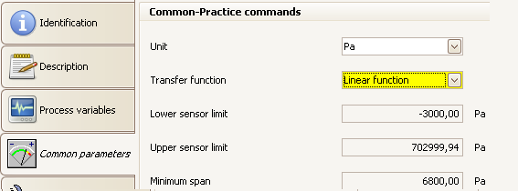
The procedure of characteristics change is described inConversion characteristics change.